Introduction:
The function of butterfly valves is to regulate or segregate the flow of a system. In a pipeline system, we use the valve to repair, cleanse, or alter liquids when there is no flow through the pipeline. This is due to its capability of initiating, stopping, or prohibiting flow.
Butterfly valves can be helpful in a multitude of sectors and industry types. These include:
- fire safety
- fuel management systems
- vacuum services
- water provision
- hydrocarbon sectors
- maritime industry
- refineries
The valve manufacturer must choose the suitable butterfly valve model from various options for specific uses. For optimal performance, butterfly valves require careful installation and regular upkeep. This post will concentrate on the basics of butterfly valves and how to install a butterfly valve. Let’s get started.
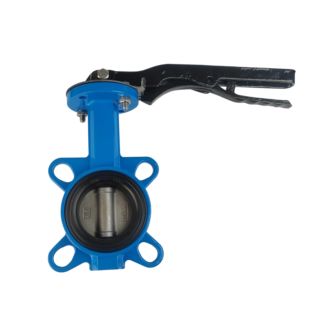
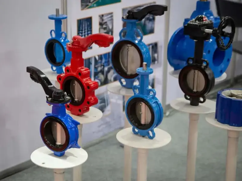
What Are Butterfly Valves?
By quarter-turning the disc, a butterfly valve regulates the passage of material through large pipe diameters. The actuator is responsible for controlling the movement of the disc. It is connected to a rod that spans the disc’s center. You can orient the disc vertically or parallel to the medium flow. The butterfly valve disc continuously engaged in the flow causes a variation in pressure. The disc attaches at the center of the pipe. An actuator and a shaft control the movement of the disc on the valve’s exterior. As the actuator spins, the disc may be parallel to or horizontal to the flow. Through pipeline pressure, high-performance butterfly valve designs enhance the interference between the seat and the disc corner.
Butterfly Valve Installation direction
Can butterfly valves be installed upside down? Concerning the flow of the medium, the butterfly valve installation direction is the way the valve should be pointed when put.
-
Vertical orientation
You can install butterfly valves vertically, with the disc opening and closing horizontally and aligning the stem vertically. You can use this setup when there is a space constraint or when you arrange the pipeline vertically.
When performing this orientation, the flow direction must be taken into account. The force of gravity may help the valve close more effortlessly when the flow direction is from bottom to top. However, if the flow is from top to bottom, closing the valve may be more difficult due to the force of gravity.
-
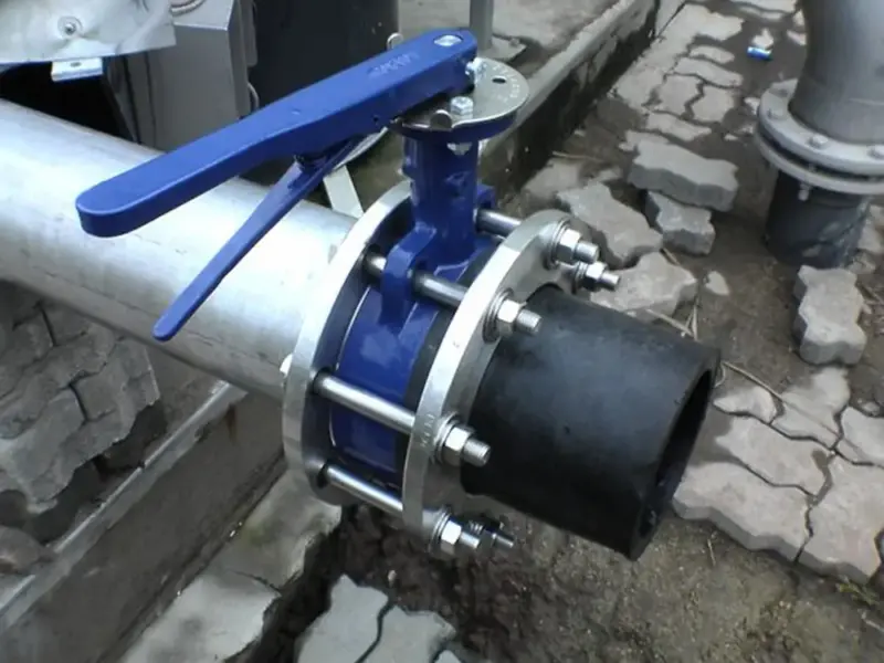
Horizontal orientation
Butterfly valves are most effective when installed horizontally. Position the stem horizontally as well. Additionally, the disc should be vertical for opening and closing. By utilizing gravity to close the valve and positioning the handle or actuator in an accessible location, this design helps with simple operation and maintenance. After understanding the directions, here are the Butterfly Valve Installation guidelines
How To Install a Butterfly Valve?
Check out the detailed butterfly valve installation guidelines to ensure you install it correctly.
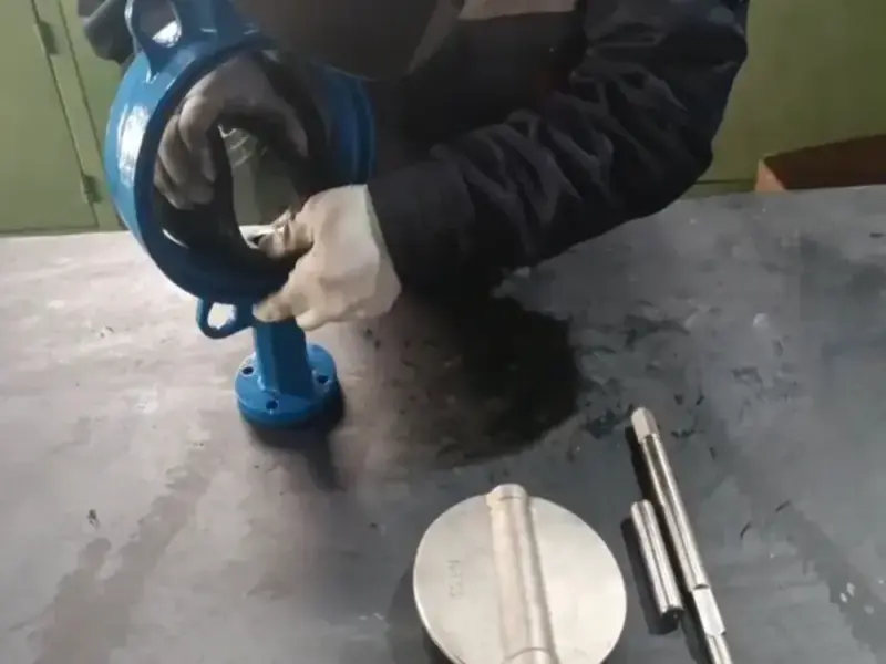
Step 1:
Install the hand wheel or lever, which is applicable, for the gear-operated valve in Step 1. Ensure the valve is closed by rotating the hand wheel or lever clockwise. The disc’s borders must be horizontal to one another.
Step 2:
If the disc is not perpendicular to the ends while using a lever type, loosen the top plate by taking out two bolts. Turn the lever counterclockwise until the disc is center and perpendicular to the ends, and then secure the top plate.
If the gearbox has gear-operated valves, you must revise the hex bolts on its side. To ensure correct operation, insert and remove the disc. If necessary, repeat this procedure for re-alignment.
Step 3:
At this point, incorporate the valve into the pipe system. Tapped lug-style butterfly valves are secured between the flanges using minuscule cap screws at the inlet and exhaust of the valves. In contrast, the wafer-style valves are affixed between the flanges using fasteners that are entirely threaded.
Step 4:
Disperse the flanges to a diameter of 3/16″, which is more significant than the face-to-face size of the valve. It prevents grime accumulation or damage to the seat’s sealing face. Determine that the pipe flange faces are devoid of extraneous material. It includes scale, filth, welding residue, or metal particles.
Step 5:
Secure the disc between the flanges, ensuring it is aligned and centered after closing it. Ensuring the upstream and downstream pipe ends are centered for the valves to function without complications. Slowly disengage the flange spreader while securing the hand-tightening flange fasteners. Moreover, ensure the valve is centered on the flanges.
Step 6:
Gradually open the valve to the fully open position to ensure the disc can move freely without any impediment. Make sure that there is no connection to the pipes or flanges. Disc interference may result from implementing valves in pipelines with smaller-than-average interior diameters. It is lined with plastic, has a thick wall, diminishing flanges, or has as-cast flanges.
Interference in a system can also occur when attaching to a quiet check or swing check. This interference can cause disruptions and hinder the smooth functioning of the system. Corrective measures like tapering or piercing the line are critical to rectifying this issue. It involves narrowing the tube to cut any obstructions causing interference. Another effective solution is incorporating a spindle.
It will act as a physical barrier to remove obstructions and ensure uninterrupted flow within the system. These corrective measures are crucial in maintaining the efficiency and effectiveness of the system. They help to eliminate any potential sources of interference and optimize its performance.
Step 7:
Tighten flange fasteners to the designated torque values after inspecting the correct operation. Use a star or crisscross pattern to distribute the fasteners.
Pump the piping to the valve and inspect for leakage in the eighth step. Use a cross-over pattern when fastening fasteners, and increase torque if discharge is observed. Installers verify that the bolts are vital for the intended purpose. Bolts must be lubricant-free, efficient, and spotless.