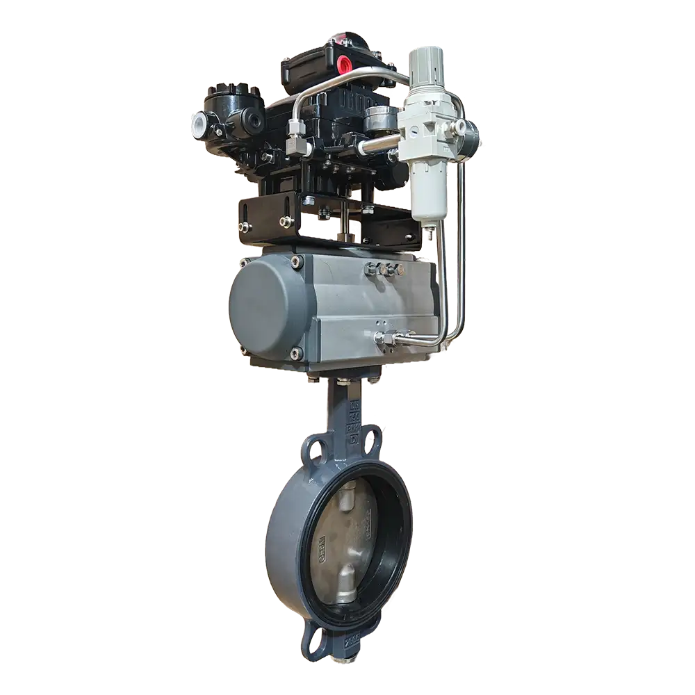
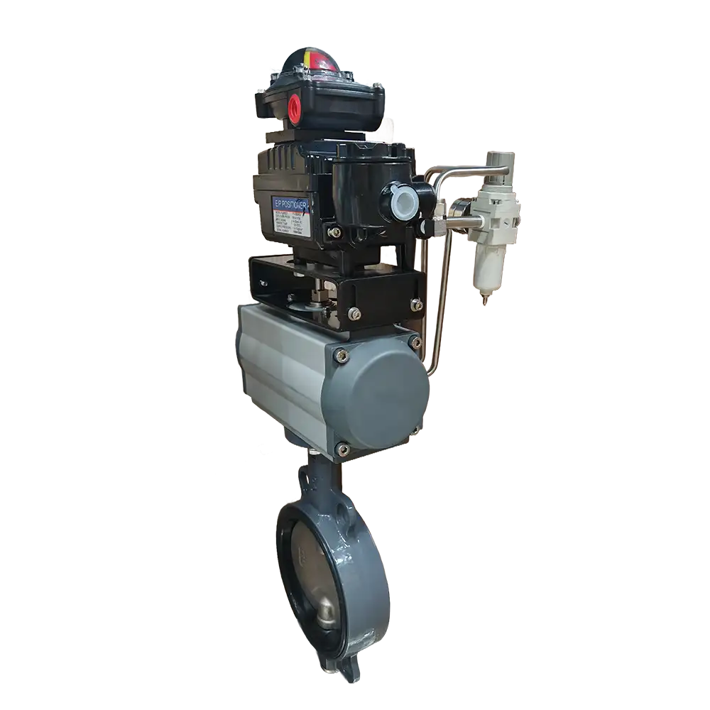
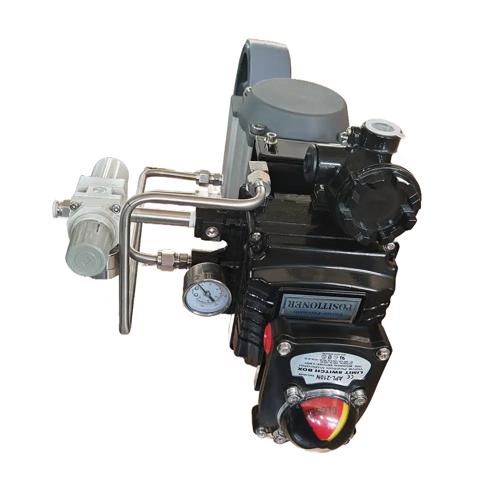
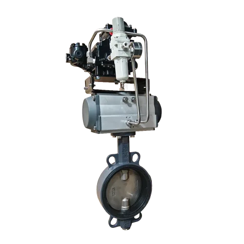
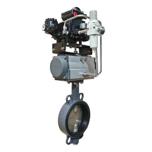
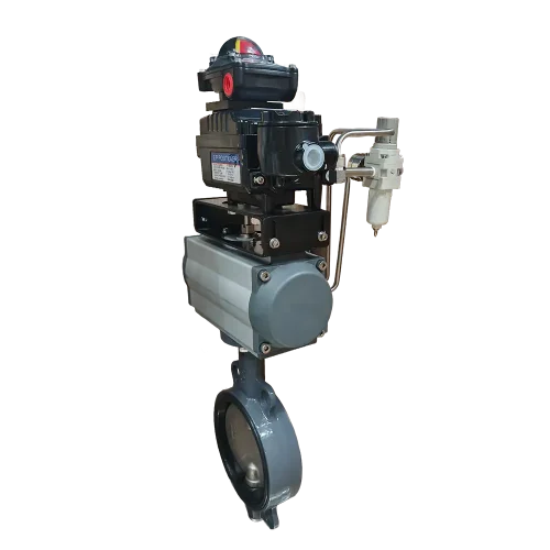
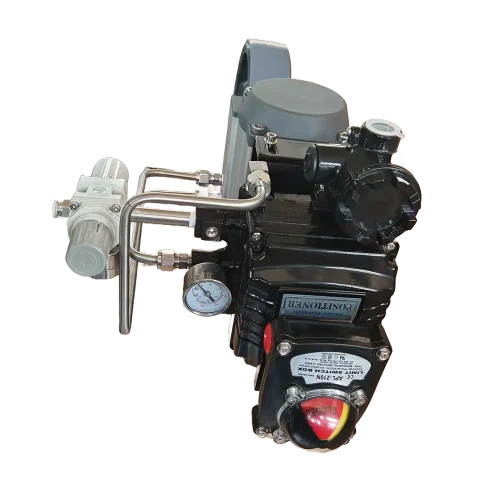

What is Fail-in-Place Positioning Pneumatic Actuator
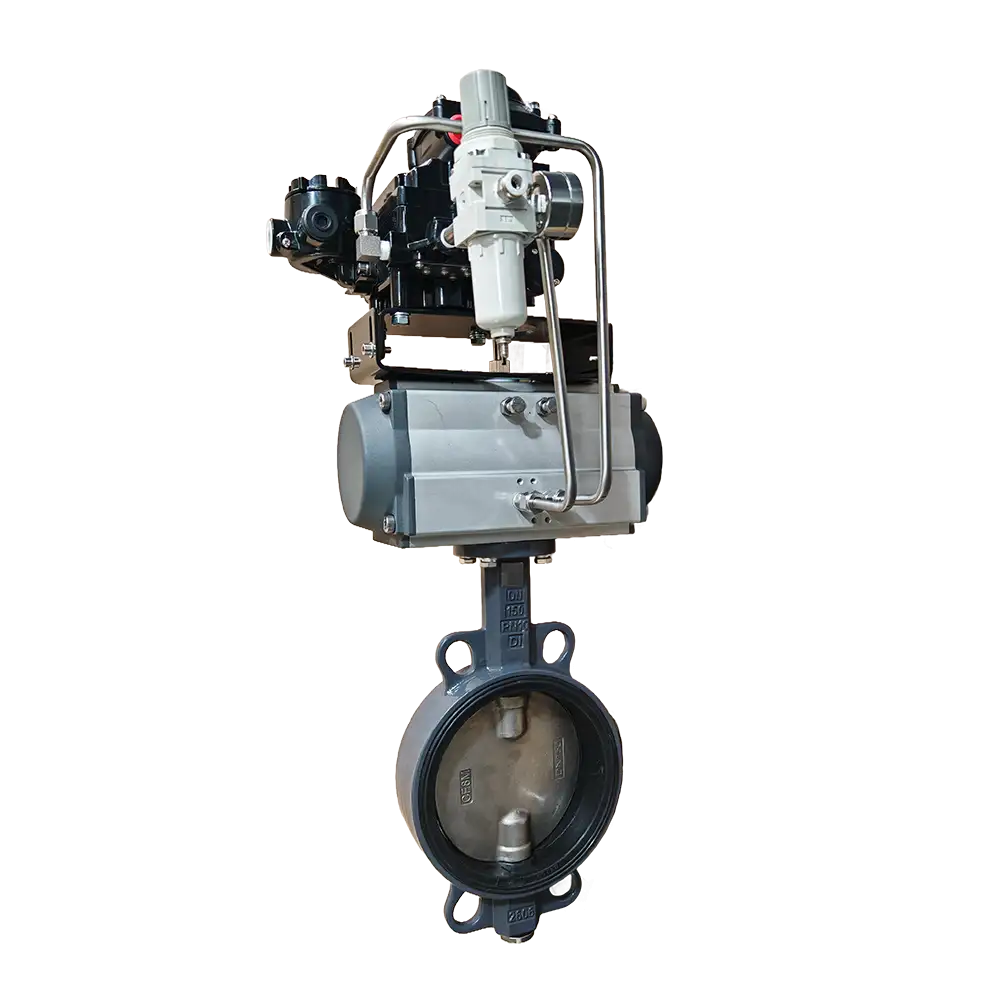
1. Position-Holding Functionality Under Three Failure Scenarios
2. Positioning During Normal Operation and Position-Holding During Failures
Features of Three-Way Fail-Safe Function Pneumatic Butterfly Valve
- During the commissioning process, the valve’s response to each of the three aforementioned failure scenarios can be verified. By testing the response to the loss of air supply, power supply, and signal—one by one—it can be ensured that the valve’s actual performance within the plant’s control sequence aligns with the intended design requirements.
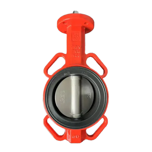
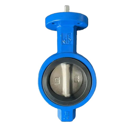
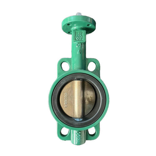
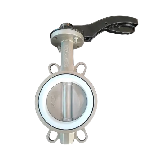
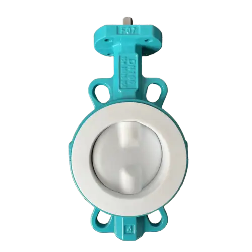
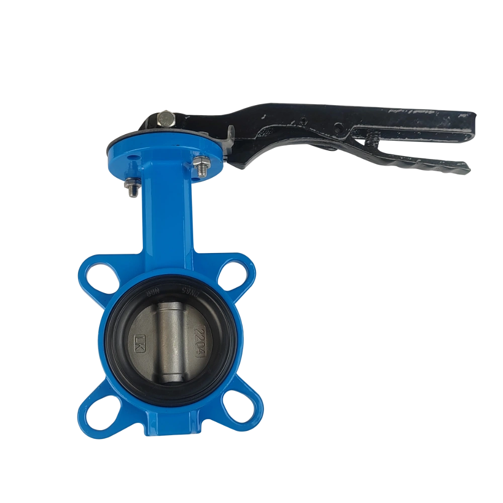
- The replaceable EPDM seat creates a resilient contact surface around the valve disc. During maintenance, this sealing element can be replaced—and the edge of the disc inspected—to restore the valve’s shut-off performance without needing to replace the functional metal components.
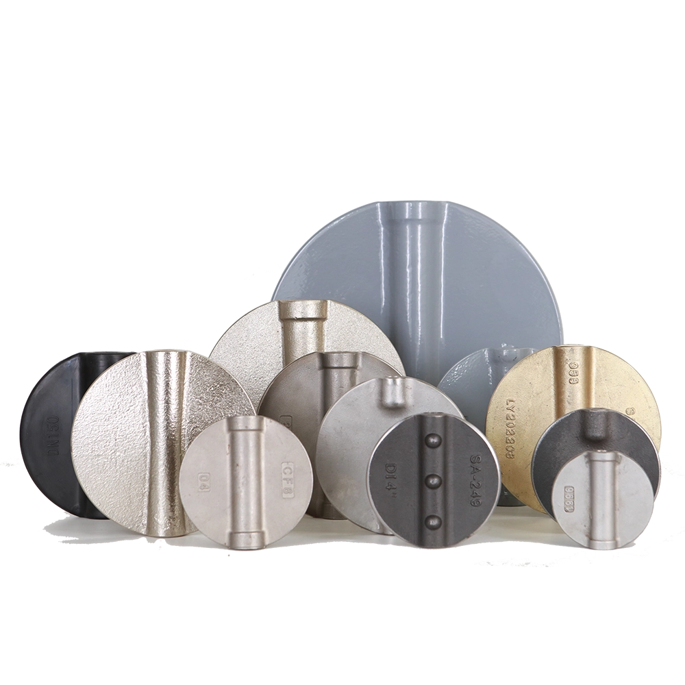
- Milwaukee-Style Valve Disc Made of CF8M Stainless Steel provides the wetted components with excellent corrosion resistance, while the disc geometry ensures smooth fluid flow through the DN150 passage. Actual pressure loss depends on the valve’s opening angle and the operating flow rate.
Technical Parameters of Pneumatic Butterfly Valve
Material Option of Air Actuated Butterfly Valve
| Part Name | Material/Method |
| Body | Ductile Iron, Casting Iron, WCB, LCB/LCC, Stainless Steel, Duplex Stainless Steel, Aluminium Bronze |
| Disc | Ductile Iron(Coated/Lined), WCB, LCB/LCC, Stainless Steel, Duplex Stainless Steel, Aluminium Bronze |
| Seat | Rubber(EPDM/NBR/VITON), Nature Rubber, Silicon Rubber, PU, HNBR, Hypalon |
| Stem | 304, 316, 420(2Cr13), 431, 1.4462, 17-4PH, Monel |
| Actuator | Pneumatic, Handlever, Worm Gear, Electric |
Standards of Wafer Butterfly Valve with Pneumatic Actuator
| ITEM | Standard |
| Design | EN593 | API609 |
| Face to Face | EN558 | ISO5752 | API608 | BS5155-4 |
| Top Flange | ISO5211 |
| Flange Drilling | PN6 | PN10 | PN16 | ASME B16.5 CL150 | JIS 10K |
| Pressure Rating | PN6 | PN10 | PN16 | PN25 | CL150 | JIS 10K |
| Tightness Test | ISO5208 | API598 | EN12266-1 |
Dimensions of Pneumatic Wafer Butterfly Valve
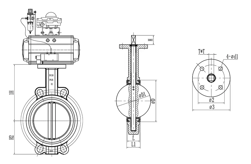
| SIZE | øD | øD1 | L | H | H1 | H2 | ø2 | ø3 | 4-ød1 | T*T |
| DN40 | 72 | 43 | 33 | 25 | 121 | 61 | 50 | 65 | 7 | 9 |
| DN50 | 76.3 | 52.8 | 42 | 25 | 131 | 66 | 50 | 65 | 7 | 9 |
| DN65 | 89 | 64.6 | 44.7 | 25 | 142 | 71 | 50 | 65 | 7 | 9 |
| DN80 | 103.9 | 79.1 | 45 | 25 | 150 | 83 | 50 | 65 | 7 | 9 |
| DN100 | 135 | 104.4 | 51.2 | 25 | 170 | 102 | 70 | 90 | 10 | 11 |
| DN125 | 159 | 123.3 | 54.4 | 25 | 184 | 117 | 70 | 90 | 10 | 14 |
| DN150 | 188.4 | 155.6 | 55 | 25 | 200 | 130 | 70 | 90 | 10 | 14 |
| DN200 | 238.2 | 202.5 | 58.8 | 35 | 240 | 162 | 70 | 90 | 10 | 17 |
| DN250 | 292.4 | 250.5 | 65.7 | 35 | 270 | 196 | 102 | 125 | 12 | 22 |
| DN300 | 344.2 | 301.6 | 76 | 35 | 310 | 216 | 102 | 125 | 12 | 22 |
| DN350 | 375.2 | 333.4 | 76.5 | 45 | 368 | 260 | 102 | 140 | 12 | 22 |
| DN400 | 439.5 | 389.6 | 85.7 | 50 | 400 | 315 | 140 | 175 | 18 | 27 |
| DN450 | 490.5 | 440.5 | 104.6 | 50 | 422 | 340 | 140 | 175 | 18 | 27 |
| DN500 | 535.4 | 491.6 | 130.2 | 55 | 480 | 379 | 140 | 175 | 18 | 32 |
| DN600 | 654.3 | 592.5 | 151.3 | 68 | 562 | 438 | 165 | 210 | 23 | 36 |
Application of Fail-in-Place Operation Air OP Butterfly Valve
1. Industrial Cooling-Water Distribution
Suitable for cooling-water branches where retaining the existing valve opening during a brief control interruption is preferable to an immediate full-open or full-closed movement. Actual cooling flow still depends on pump operation and available differential pressure.
2. Water-Treatment Flow Balancing
Applicable to compatible water streams where pneumatic positioning adjusts distribution between treatment units or parallel branches. Position retention helps avoid an additional flow disturbance caused by unintended disc movement during a control fault.
3. Heat-Exchanger Water Circuits
For adjusting water flow through heat-exchanger branches within the approved seat temperature range. A fail-in-place arrangement may be selected where the process requires the current valve setting to be retained while supervisory controls manage the interruption.
4. Industrial Process-Water Headers
Suitable for remotely controlled water branches serving production equipment. Holding the previous opening can give operators time to assess the fault and coordinate recovery with pumps and downstream equipment.
5. HVAC Water and Compatible Glycol Circuits
Applicable to chilled-water and heating-water systems requiring pneumatic positioning and a defined hold response. Glycol concentration, treatment additives and operating temperature must be checked against the selected EPDM compound.
Fail-in-place operation should be selected only where retaining the existing valve position is appropriate for the process. All applications require confirmation of wetted-material compatibility and operating limits.
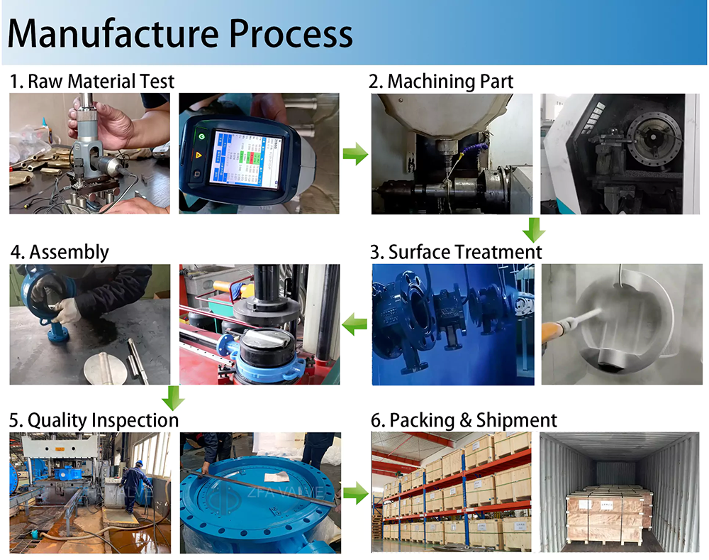
Manufacture Process of Butterfly Valve
Certificates of ZFA VALVE-Butterfly Valve Manfuacturer in China
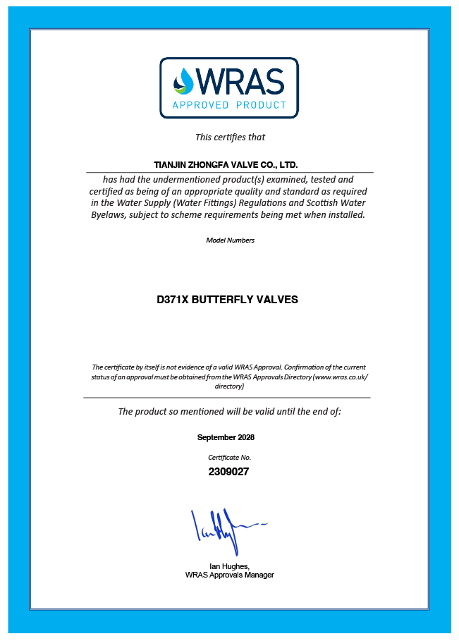
WRAS
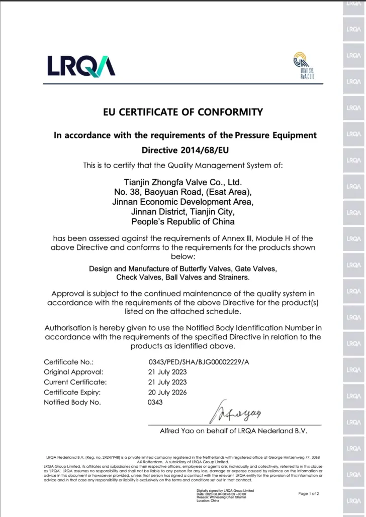
CE
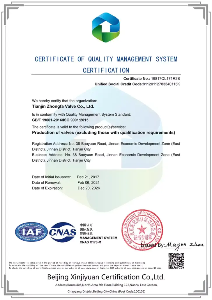
ISO 9001
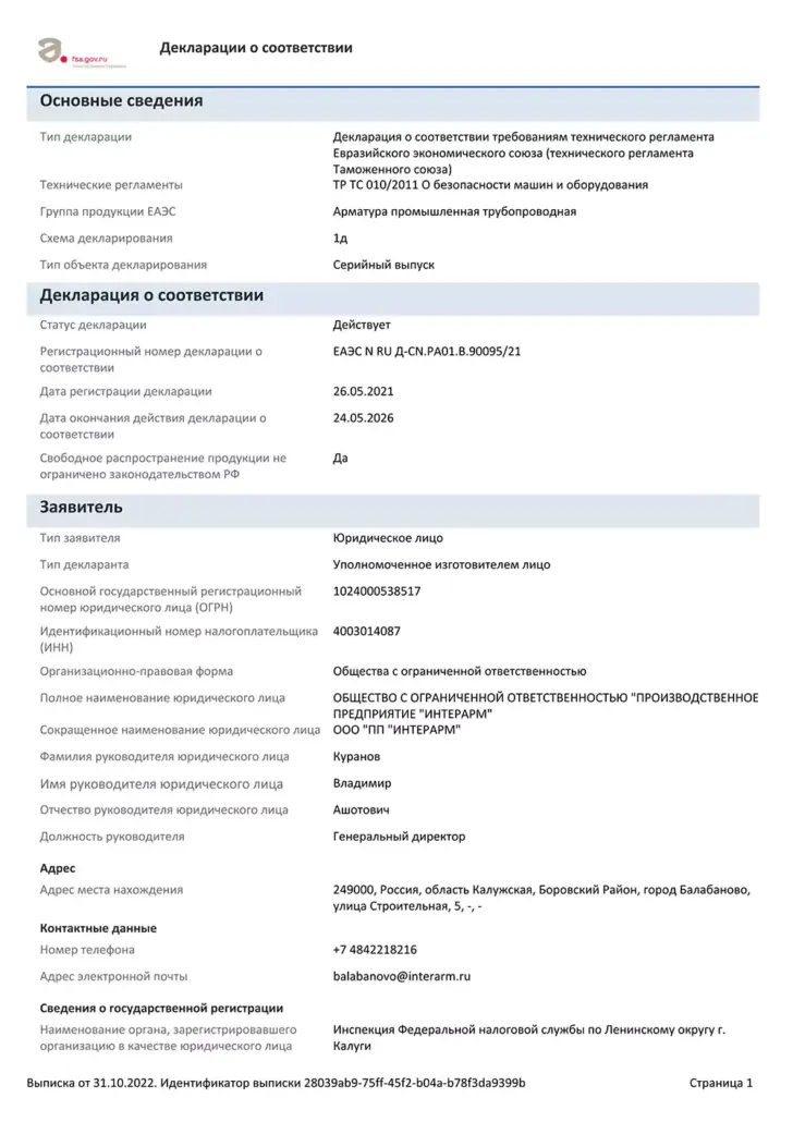
EAC Russia
FAQ of Pneumatic Operated Butterfly Valve
No. A fixed valve position (or disc angle) does not guarantee a constant flow rate. Changes in pump output, upstream pressure, or downstream resistance can still cause the flow rate to vary. The “hold” (or “fail-in-place”) function merely restricts valve movement; it is not a substitute for active flow control.
The duration for which a valve can maintain its position depends on the airtightness of the pneumatic circuit, the condition of the actuator, the process torque, and the operating pressure. When determining this duration, an allowable angular deviation should be specified and verified under typical operating conditions. Never assume that a valve can remain in a fixed position indefinitely without drifting.
The outcome depends on the selected control logic. The valve assembly may automatically resume its intended position, or it might require a manual reset. If the command signal present upon restoration differs from the position held during the outage, the valve may move. Therefore, the restart sequence must be coordinated with the associated process equipment.
No—not if the emergency conditions require the valve to close completely. If a valve remains in a partially open state, the flow path remains unobstructed. If the process requires automatic isolation during an emergency, a dedicated and validated shutdown solution must be implemented.
Required information includes fluid composition, operating temperature, pressure range, maximum pressure differential, and the desired flow range. Additionally, specifications for minimum instrument air pressure, power supply, command signals, required hold duration, allowable positional drift, and desired recovery behavior are necessary. These detailed parameters ensure that the actuator, positioner, and locking circuit are selected as a cohesive, integrated system.