
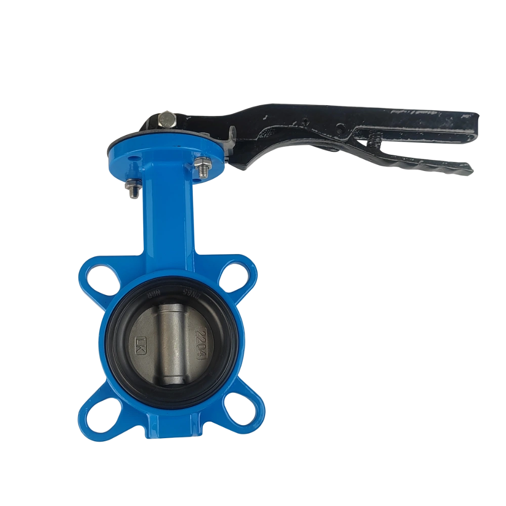
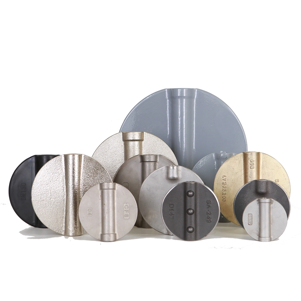
The selection of an appropriate butterfly valve disc thickness should be constrained by requirements for strength, deformation, and sealing under the maximum operating pressure differential. Subsequently, the disc profile, hub, and reinforcement structures should be optimized to minimize flow resistance.

Because the butterfly disc is permanently positioned in the center of the flow passage, it occupies a portion of the cross-sectional area even when the valve is fully open.
Consequently, the thickness represents a critical trade-off between “flow obstruction” and “pressure-bearing capacity”:
- ✘ An excessively thick disc increases flow resistance, reduces the flow coefficient (Cv/Kv), and raises system energy consumption.
- ✘ Conversely, an excessively thin disc may undergo significant deformation under pressure, compromising the seal, increasing operating torque, and potentially leading to vibration or fatigue issues.
True balance is not a matter of “thinner is always better” or “thicker is always safer.” Rather, it requires a quantitative, application-specific design—placing material precisely where it is needed for structural load-bearing while minimizing unnecessary flow obstruction.
When procuring such valves, one should not merely compare thickness or weight; instead, it is essential to evaluate the flow coefficient at specific opening angles, the allowable pressure differential, the operating torque, and the supporting validation data.
1. How thickness affects flow resistance and flow performance
The flow resistance coefficient (ζ) and the flow coefficient are primarily influenced by the projected thickness of the butterfly disc, its profile shape, and the protrusions around the valve stem.
A thick, flat-type plate disc creates a large wake and flow separation zone when fully open, typically resulting in a high ζ value. In contrast, a lens-type or streamlined profile type can significantly reduce the separation zone, thereby lowering pressure loss.
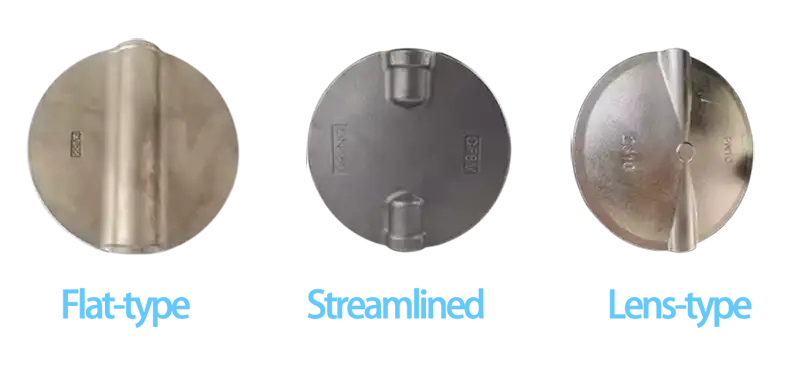
Both engineering experience and numerical simulations demonstrate that, for a given nominal diameter, reducing the disc thickness—combined with profile optimization—can lead to a substantial decrease in flow resistance when the valve is fully open. Comparisons between CFD (Computational Fluid Dynamics) simulations and experimental tests indicate that an optimized, thin, streamlined disc can reduce pressure loss by 20%–60% across various opening angles. At small opening angles, the impact of disc thickness is more pronounced because the flow area is already restricted. Once the opening angle exceeds approximately 40°–50°, the relative influence of thickness diminishes, while the importance of the disc profile and the arrangement of stiffening ribs increases.
Note: Pursuing a thinner design does not automatically equate to a higher $C_v$ (flow coefficient). The AWWA C504 standard provides specific recommendations for large-diameter butterfly valves: the disc should not feature transverse ribs, and its thickness should generally not exceed 2.25 times the valve stem diameter.
2. Relationship Between Thickness, Structural Strength, and Rigidity
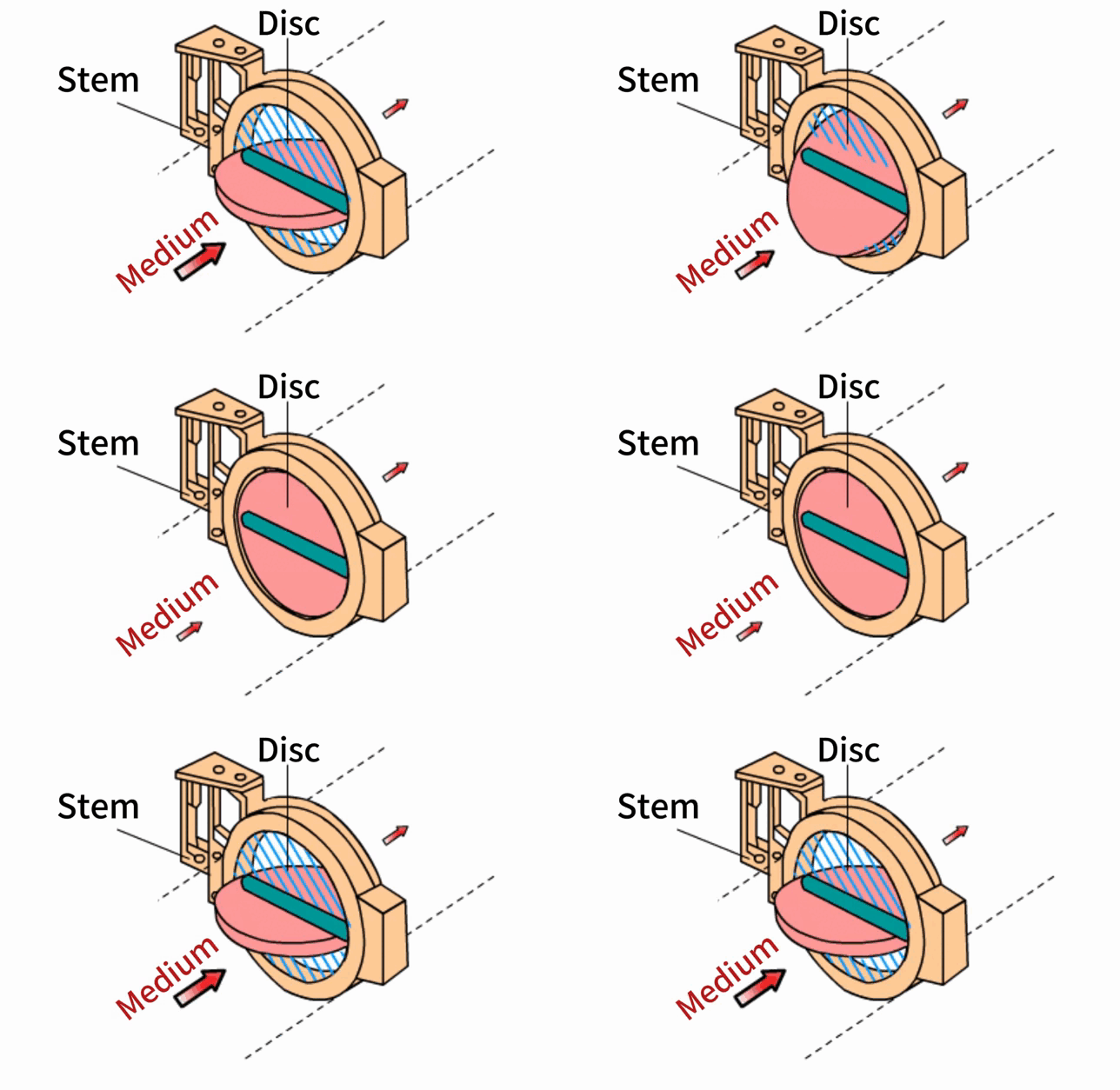
In the closed position, the valve disc is subjected to a bending moment resulting from the pressure differential of the medium on either side; the thickness at the center is the primary parameter governing bending stress and deflection. Increasing the thickness directly enhances the section modulus, thereby reducing both stress and deformation.
In practical design, the center thickness is typically estimated using empirical methods or formulas for simply supported circular plates. This initial estimate is then adjusted by incorporating a corrosion allowance, casting/machining tolerances, and a safety factor. The final thickness is determined by considering both the material properties—as the elastic modulus and allowable stress vary significantly between materials such as ductile iron, stainless steel, and alloy steel—and the structural configuration (e.g., integrally cast, or a welded frame with a skin/plate).
3. Distinguishing Between Strength and Rigidity
STRENGTH
Concerns whether the material will yield or fail.
RIGIDITY
Concerns whether the deformation under load becomes excessive.
Even in the absence of permanent damage, elastic deformation of a butterfly disc can alter the contact conditions at the edges and the valve seat, potentially leading to insufficient or excessive local sealing pressure.
This is particularly critical for large-diameter butterfly valves. Since a larger diameter results in a greater pressurized surface area under the same pressure differential, one cannot simply scale up the design of a smaller butterfly disc.
Engineering studies focused on the optimization of butterfly discs typically incorporate both structural strength and pressure loss as constraints, rather than aiming solely for the lowest possible weight.
4. Can the use of higher-strength materials automatically allow for a reduction in component thickness?
The answer is a definitive “no!”
We frequently receive inquiries from OEM clients asking: “If we switch to a higher-strength material, can we make the butterfly disc thinner?”
Not necessarily. It depends on whether the design is constrained by strength, stiffness, or corrosion resistance. An increase in yield strength does not imply a proportional increase in the modulus of elasticity. If the primary concern is deformation at the sealing edge, upgrading the material may not compensate for the loss of stiffness resulting from a reduction in thickness.
Furthermore, factors such as casting quality, heat treatment condition, machining tolerances, and corrosion allowance must be taken into account. Even if the material grade is the same, it cannot substitute for the verification of the actual casting quality.
Achieving a reasonable reduction in weight typically requires a redistribution of cross-sectional material—for instance, by retaining thickness at the hub and critical load-bearing areas while optimizing (reducing) it in non-critical zones—followed by a re-validation of flow performance. Additionally, the use of stiffening ribs comes with trade-offs: they alter local flow fields and, depending on the medium, may increase the risk of sediment accumulation or make cleaning more difficult.
5. Practical Engineering Strategies for Balancing Design
5.1 Tiered Approach Based on Operating Conditions
1. Low-pressure, high-flow: Prioritize a streamlined, thin-profile butterfly disc, focusing on the $C_v$ value.
2. Medium-to-high-pressure shut-off: Increase the thickness at the center or incorporate reinforcing structures.
3. Particulates or erosive media: Ensure sufficient thickness to account for wear (corrosion/erosion allowance).
5.2 Prioritizing Profile and Rib Optimization
Employing lens-shaped or wedge-shaped profiles, utilizing symmetrically arranged longitudinal ribs, and eliminating unnecessary transverse ribs can enhance stiffness without requiring an increase in thickness.
5.3 Matching Materials with Manufacturing Processes
High-strength materials allow for thinner cross-sections while maintaining the same safety margin. Large-diameter butterfly valves often employ a “frame-and-skin” design to ensure structural strength while managing weight.
5.4 Essential Verification Measures
Nominal thickness alone is insufficient. Suppliers should provide $C_v/zeta$ curves and stress/deformation analysis results for the closed position. Dimensional re-verification should be conducted following hydrostatic testing.