
As butterfly valves play an increasingly significant role in control systems, end-users have shifted their focus from prioritizing cost-effective, standard actuation configurations to adopting safer, more reliable actuation solutions.
This article introduces a type of pneumatic actuator equipped with a “fail-in-position” (or “stay-put”) positioner—a system designed to maintain the valve’s current position in the event of a utility failure.
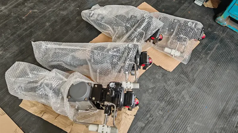
When selecting a pneumatic valve, beyond standard considerations such as torque, air supply pressure, and operating speed, one must also address a critical question: what should the valve do if the air supply, power supply, or control signal is suddenly lost—a scenario collectively referred to as a “triple-failure” (or “three-loss”) event?
Depending on the specific application, a valve might need to close immediately, open fully, or—in some cases—remain at its current degree of opening. Pneumatic actuators with “fail-in-position” capability are designed specifically for this third requirement.
Their value lies in preventing unintended valve movement during a malfunction. By holding the valve in place, they provide time for the system to diagnose the fault, switch control strategies, or initiate a safe shutdown—serving as a “final line of defense” for safety in process industries.
1. What is “Fail-in-Position” (Stay-Put) Operation?
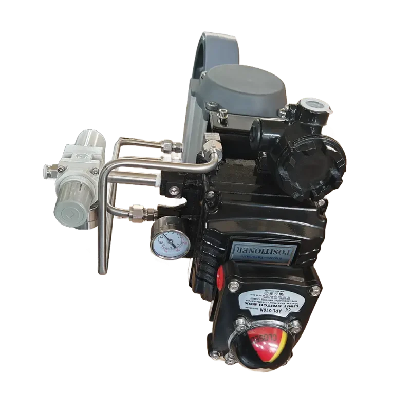
“Triple-failure” (or “three-loss”) refers to the loss of one or more of the following: air supply, electrical power, or the control signal.
“Fail-in-position” actuator (or “stay-put”) means that, under these failure conditions, the valve is held at or near its position prior to the failure, with any deviation kept within a specified, agreed-upon range. This is a technically demanding mode of operation; at the instant a failure occurs, the valve must be effectively “locked” at the exact opening position it occupied at that moment.
For example, if a butterfly valve is operating at a 40% opening position and the control signal is lost, the system ceases further adjustment and instead enters the “fail-in-position” state.
Note: The 40% figure here refers to the valve’s travel or degree of opening, not to 40% of its rated flow capacity.
While “fail-in-position positioner” is a common term, achieving this functionality typically requires the integration of a positioner, a pneumatic actuator, pneumatic locking components, and other related control accessories.
1.1 Loss of Air Supply
When the pressure in the plant’s main air supply network drops below a defined safety threshold, the air pressure within the pneumatic actuator may deplete due to leakage. Without intervention, a spring-return actuator would be forced to its default (zero) position, while a double-acting actuator would enter an uncontrolled, “floating” state as the pressure differential across its chambers disappears.
Implementation: A “lock-up valve” is typically installed in the pneumatic line. When the supply pressure falls below a critical value, the internal spring force of the lock-up valve overcomes the air supply pressure, instantly isolating the pneumatic line between the positioner and the actuator cylinder, and sealing the air chambers on both sides of the piston. Due to the low compressibility of the gas and an effective seal, the piston is held firmly in place, “locking” the valve in its current position.
1.2 Loss of Electrical Power
Smart positioners and solenoid valves rely on electrical power to operate. If the power supply is interrupted, the internal microprocessor and the I/P (current-to-pneumatic) converter will cease to function.
Implementation: Most modern smart positioners utilize piezoelectric valves or integrated power-loss detection circuits. Upon detecting a loss of power, the internal control logic triggers a solenoid valve or a pneumatic switching module, which in turn activates the lock-up valve to “freeze” the current output air pressure within the actuator cylinder.
1.3 Loss of Control Signal
If the output signal from a DCS or PLC system is interrupted—for example, due to a communication failure (such as a 4mA signal loss)—the system must not simply default to a fully open or fully closed state (the appropriate response is determined by a Hazard and Operability Analysis, or HAZOP).
Implementation: Once the internal software or hardware comparator of a smart positioner detects the loss of the control signal, it initiates a pre-configured “fail-safe” strategy. If the strategy is set to “fail-in-place” (hold position), the positioner will shut off its output control air line, working in conjunction with the lock-up valve to lock the valve in its current position. Some products feature integrated functionality, while others require external accessories; therefore, one cannot determine whether a device supports “position retention upon triple-failure” (loss of air, power, or signal) based solely on the term “smart positioner.”
2. How do pneumatic actuators achieve positioning and position retention?
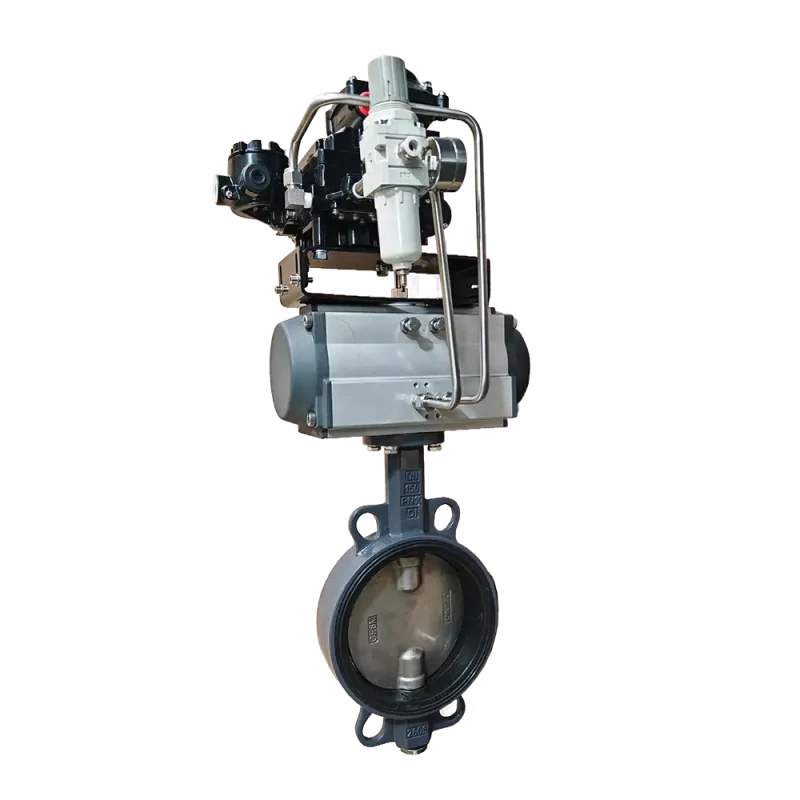
During normal operation, the positioner receives control commands, compares the target opening with the actual valve position, and adjusts the flow of compressed air into or out of the actuator to rotate the valve shaft to the desired angle.
In the event of a failure, the position-retention system must prevent the actuator from moving further.
Taking a common pneumatic locking mechanism as an example: when the air supply pressure falls below a set threshold, the locking component shuts off the relevant air paths, effectively trapping the air within the actuator chambers to maintain the current position.
The response to a loss of power or a loss of control signal depends on the positioner and its associated control loop. Since the triggering mechanisms for these three types of failures (loss of air, power, or signal) may differ, each must be verified individually.
It should be noted that pneumatic locking requires a certain response time. A gradual drop in pressure versus a sudden loss of air supply may result in different final valve positions; therefore, “position retention” should not be interpreted as an instantaneous, deviation-free stop under any failure condition.
3. How does this differ from a standard pneumatic actuator?
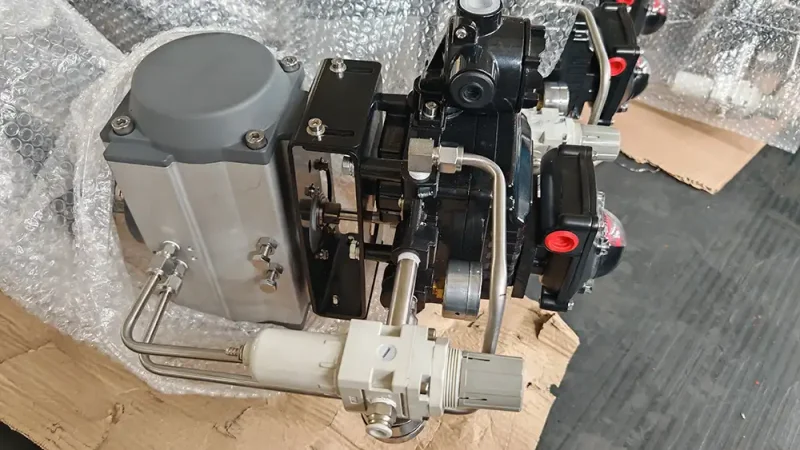
If the main plant air supply pressure drops below a defined safety threshold—and no intervention occurs—the air pressure within the pneumatic actuator will eventually deplete due to leakage, causing a spring-return actuator to force the valve to its default (zero) position.
3.1 Standard Pneumatic Actuators
Standard double-acting actuated butterfly valve rely on compressed air to drive motion in both directions. If the air supply is lost, the valve may remain stationary for a time, but forces exerted by the process medium or internal leakage could still cause it to shift.
Single-acting, spring-return actuators use a spring to drive the valve toward a predetermined open or closed position in the event of a specified failure.
3.2 Actuators with Triple-Failure Position Retention
The objective of a “triple-failure position retention” system is to maintain the current valve position under defined failure conditions. The choice of system should be based on specific process requirements; it is a misconception to assume that more features automatically equate to greater safety.
For instance, a pipeline requiring the complete cutoff of feed must be able to close reliably, whereas a water line that needs to maintain its current distribution state might be a suitable candidate for position retention.
4. For which applications should “fail-in-place” (maintaining the current valve position) be considered?
* Industrial cooling water branches: In scenarios where the control system experiences a brief interruption while the circulation pump continues to operate, maintaining the existing valve position helps prevent the additional disturbances that would otherwise be caused by the valve suddenly closing.
* Water treatment distribution piping: In systems where multiple parallel branches rely on valves to distribute water, the sudden full opening or closing of one valve could disrupt the operating conditions of other branches. Maintaining the current valve position allows the existing settings to be preserved temporarily.
* Heat exchangers and process water systems: For branches that require continuous regulation but can tolerate a brief period at the current setting, “fail-in-place” provides a buffer, giving operators time to investigate and address faults.
4.1 Typical Applications:
Boilers, steam systems, and high-temperature/high-pressure systems: Significant, uncontrolled valve movement in these environments could lead to pipeline ruptures or even serious safety incidents.
Chemical, petrochemical, and hazardous materials pipelines: A malfunction causing a valve to swing fully open or fully closed could result in leaks, or in more severe cases, explosions or fires.
Long-distance oil and natural gas transmission pipelines: Excessive pressure fluctuations can lead to critical operational issues.
Continuous production lines (e.g., in the pharmaceutical, food, or metallurgical industries): Unplanned stoppages can result in substantial economic losses.
However, if system requirements dictate that water supply must be stopped, hazardous media must be isolated, or an emergency bypass must be opened during a failure, “fail-in-place” cannot serve as a substitute for the necessary safety-related fail-safe actions.
5. If the valve position is maintained, why might the flow rate still change?
This is a frequently overlooked aspect when selecting “fail-in-place” functionality.
Valve opening is only one of the factors that determine flow rate. Flow is also influenced by pressures upstream and downstream of the valve, as well as the overall state of the piping network. Even if the valve’s internal component (such as a butterfly disc) remains at a fixed angle, events like a pump shutdown, the activation of a backup pump, or the closure of other branches can still alter the flow rate through the valve.
Think of a water faucet: even if the handle remains untouched, a drop in upstream supply pressure will still result in a decrease in the water flow.
Taking a cooling water system as an example: suppose a valve is held at a specific opening, providing sufficient cooling for the equipment. If a fault occurs and the valve successfully remains in that position, but the circulation pump simultaneously shuts down, the cooling water flow rate could still drop significantly.
Therefore, while “fail-in-place” can prevent unintended movement of the valve itself, it cannot guarantee the continued stability of the entire process.
6. Is the original valve position still appropriate after a fault occurs?
Again, consider a cooling water system: if the equipment load continues to rise, the existing cooling water flow may become insufficient; conversely, if downstream demand decreases, maintaining the original supply conditions may no longer be appropriate. A valve position that was suitable before a fault is not necessarily a safe or correct position for all post-fault scenarios. This means that when selecting a “fail-in-place” (hold-position) strategy, three questions must be addressed:
– How will the pump and other critical equipment respond in the event of a failure?
– For how long does the process allow the valve to remain at its current opening?
– What action will the system take once this duration is exceeded?
“Fail-in-place” should be treated as a defined step within the failure-handling protocol—supported by monitoring of flow, pressure, or temperature—rather than as a guarantee that the system can continue to operate as normal indefinitely.
7. How can “fail-in-place” capability be translated into an enforceable acceptance requirement during procurement?
Procurement specifications should clearly define the operating load, the required duration for holding the position, the permissible degree of deviation, and the expected behavior upon system recovery.
During acceptance testing, scenarios such as loss of air supply, loss of power, and loss of control signals should be simulated—ideally with the valve set to a representative intermediate position—to observe actual valve displacement. Testing should distinguish between the initial deviation occurring at the moment of failure and any subsequent, gradual drift over time.
The recovery process must also be evaluated: once air supply or control signals are restored, does the valve automatically resume following the control command, or does it require a manual reset? Furthermore, if there is a significant discrepancy between the current (held) position and the restored control command, could this trigger an abrupt, sudden movement?
A pneumatic actuator truly suitable for field use with “fail-in-place” functionality must exhibit clear, verifiable behavior across all three stages: the onset of the failure, the holding phase, and the subsequent recovery.